
ANSI Compliant Electrical Packages for TRMs
ANSI 2017 ELECTRICAL PACKAGE FOR FIELD INSTALLATION (PRODUCTION TRMS)
The KMC fully ANSI 2017 compliant electrical package includes a main electrical box, a primary control station, a secondary control station, two (2) E-Stop buttons, a feed roll safety cable assembly, home position holders for the washup stick, and the assorted sensors that are associated with the NGSIS (Nip Guard Safety Interlock System). When KMC supplies this electrical package for installation in the field, the primary control station, and the secondary control station, are both mounted on support arms (stainless steel) that are an integral part of the main electrical box. The washup stick home position holders are also mounted on the main electrical box. Typically, the main electrical box is then attached to the mill frame (motor side), and it is caster mounted, so that it can swing away when the TRM is being serviced. Although best practice would be to install an inverter duty motor, most field installations leave the existing motor in place, with the package hooked up to the motor’s high speed leg. Photos of a used (remanufactured) Kent 13”x32” Mid Production TRM with this type of electrical package are shown below. 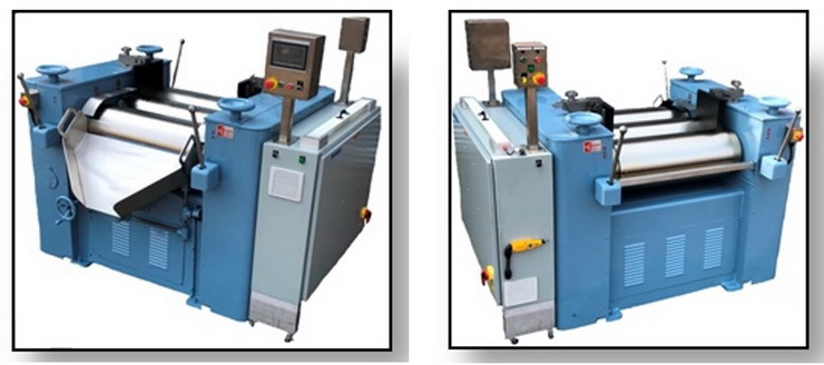
ANSI 2017 ELECTRICAL PACKAGE FOR FIELD INSTALLATION (LAB TRMS)
The KMC fully ANSI 2017 compliant electrical package includes a main electrical box, a primary control station, a secondary control station, home position holders for the washup stick, and the assorted sensors that are associated with the NGSIS (Nip Guard Safety Interlock System). When KMC supplies this electrical package for installation in the field, the primary control station, and the secondary control station in a single two-sided stainless steel enclosure, mounted on a single support arm (stainless steel) that is an integral part of the main electrical box. The washup stick home position holders are also mounted on the main electrical box. Typically, the main electrical box is then attached to the mill frame (motor side). Although best practice would be to install an inverter duty motor, most field installations leave the existing motor in place, with the package hooked up to the motor’s high speed leg. Photos of a used (remanufactured) ANTHONY 4”X8” TRM with this type of electrical package are shown below. 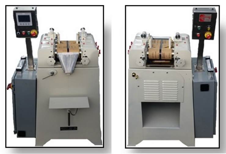
ANSI 2017 ELECTRICAL PACKAGE ON TRMS SHIPPED FROM THE KMC SHOP (PRODUCTION TRMS)
The KMC fully ANSI 2017 compliant electrical package includes a main electrical box, a primary control station, a secondary control station, two (2) E-Stop buttons, a feed roll safety cable assembly, home position holders for the washup stick, and the assorted sensors that are associated with the NGSIS (Nip Guard Safety Interlock System). When installed on a used (remanufactured) TRM, a new TEFC inverter duty motor is also included. Drawings of the primary control station, and the secondary control station, are shown below.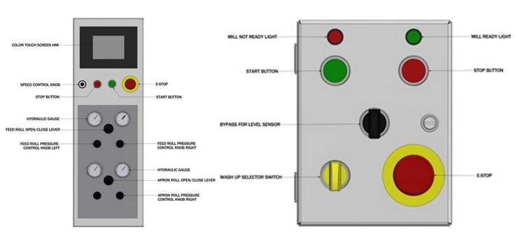
On a STANDARD CONFIGURED used (remanufactured) TRM, the primary control station is located on the apron side of the TRM, to the left of the apron. The secondary control station is located on the feed side of the TRM, to the left of the rolls. Photos of a STANDARD CONFIGURED used (remanufactured) Day 14”x30” Mid Production TRM, are shown below.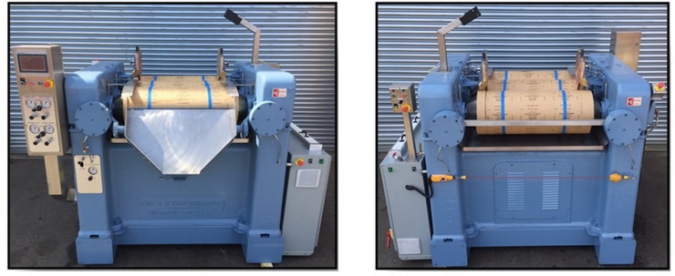
The primary control station includes a color touch screen HMI. When the TRM is powered up, the HMI will look first go to its SLEEP SCREEN, shown below. 
Touching the MAIN SCREEN rectangle, will cause the MAIN SCREEN to appear, and this MAIN SCREEN is shown below.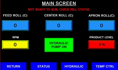
The MAIN SCREEN displays the following information.
1) MILL STATUS MESSAGE (Mill ready to run, or mill not ready to run)
2) ROLL TEMPERATURES (Each roll temperature is displayed, individually)
a. If the actual roll temperature differs significantly from the set temperature, the temperature display will flash red.
3) APRON ROLL SPEED (RPM)
4) PRODUCT LEVEL IN THE FEED NIP (shown as a percentage)
5) HYDRAULIC PUMP (This rectangle will turn on and off the hydraulic pump, as well as displaying if it is on or off)
6) CHANGE SCREEN RECTANGLES (There are several of these rectangles, located at the bottom of the screen)
a. TEMPERATURE (Pressing this rectangle will bring the operator to the TEMPERATURE CONTROL SCREEN)
b. HYDRAULIC (Pressing this rectangle will bring the operator to the HYDRAULIC CONTROL SCREEN)
c. STATUS (Pressing this rectangle will bring the operator to the MILL STATUS SCREEN)
d. RETURN (Pressing this rectangle will bring the operator back to the SLEEP SCREEN)
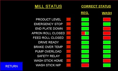
Whenever the MILL STATUS MESSAGE shows “MILL NOT READY TO RUN, CHECK MILL STATUS”, the operator should touch the STATUS rectangle on the MAIN SCREEN. The MILL STATUS SCREEN will appear, as shown below. This screen displays the correct status for each sensor, for the REG (normal running), and for WASH (running in WASHUP MODE). This screen also displays the actual status for each sensor, in real time. By viewing this screen, the operator can easily determine why the mill is not ready to run, and he can correct the problem. When all sensors are correct, the operator will touch the RETURN rectangle, to get back to the MAIN SCREEN.
By touching the TEMP CONTROL rectangle on the MAIN SCREEN, the operator can access the ROLL TEMPERATURE CONTROL SCREEN. This screen displays actual roll temperature for each roll, in real time. This screen displays and controls the set point for each roll. This screen also displays inlet water temperature. The operator can change any temperature set point by touching the desired set point rectangle. This screen also displays temperature in either F or C. This can be switched from a password protected screen, accessed from the SLEEP SCREEN. The ROLL TEMPERATURE CONTROL SCREEN is shown below.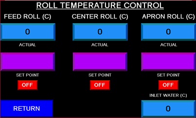
By touching the HYDRAULIC rectangle on the MAIN SCREEN, the operator can access the HYDRAULIC SCREEN. This screen displays APRON NIP pressure, FEED NIP pressure, APRON KNIFE pressure, and SYSTEM pressure. It also shows the operator when the hydraulic filter needs to be replaced, and when the hydraulic oil level is low. The operator can also turn on/off the hydraulic pump from this screen. The HYDRAULIC SCREEN is shown below.