Non–Repeatability Options for Three Roll Mills (TRMs)
ENDPLATE SYSTEMS
There are three (3) types of endplate systems employed on TRMS, and for the purposes of this discussion, I will call these KENT style endplates, or DAY style endplates, or ANTHONY style endplates. Drawings of each endplate style are shown below.
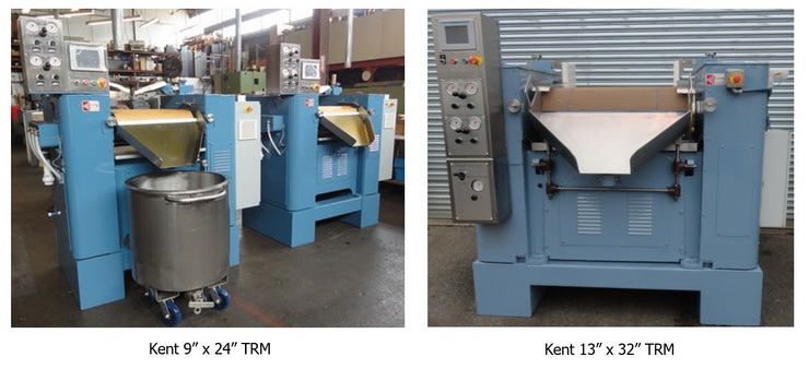
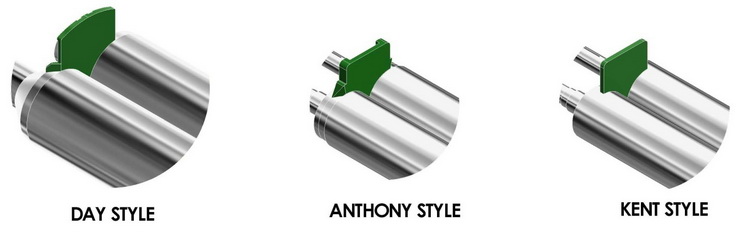 KENT style endplates ride just above the surface of the roll. These are designed to allow a small amount of product to migrate under the endplate, thereby fully coating the roll ends, until the product transfers to the apron roll. As these endplates wear, more product will migrate outward, and to mitigate against “spitting”, the endplates can be moved inward toward the center of the roll. As these endplates never actually come in contact with the roll, they generate less heat than other types of endplates, and so this design is best for very heat sensitive products. This design also has the benefit of easy installation, as this design does not require fitting with ground glass. KENT style endplates do not allow for mixing in the feed nip.
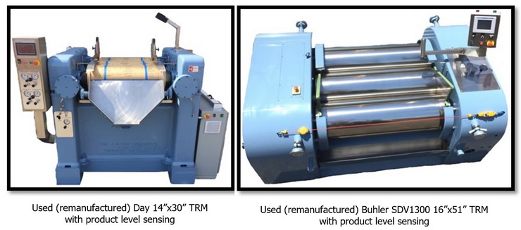
ANTHONY style endplates (also used on BUHLER TRMS) ride on the undercut of the rolls, and seal by the endplate pressing against the vertical side of the roll. As these endplates do actually contact the roll, they do generate more heat than the KENT style endplates. This design also has the benefit of easy installation, as this design does not require fitting with ground glass. ANTHONY style endplates do allow for mixing in the feed nip.
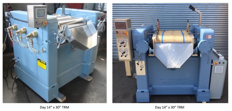
DAY style endplates ride (also used on LEHMANN TRMS) ride on the bevel of the roll, and these endplates must be “lapped” onto the bevel, making a water tight seal. As these endplates do actually contact the roll, they do generate more heat than the KENT style endplates. This design is not ready to install, as they do require fitting (lapping) with ground glass. DAY style endplates do allow for mixing in the feed nip.
FEEDING DEVICES FOR THREE ROLL MILLS
There are quite a few different ways to get your product into the feed nip on a TRM. This can be as simple as manually pouring product from a 5 gal. pail, or it can involve the use of a feeding device. The decision as to how to solve the feeding problem will depend on the viscosity of the product, the frequency of change-over to different products, color changes, and how easy/hard is the cleaning procedure. The typical TRM feeding devices are described below.
CAN TILTERS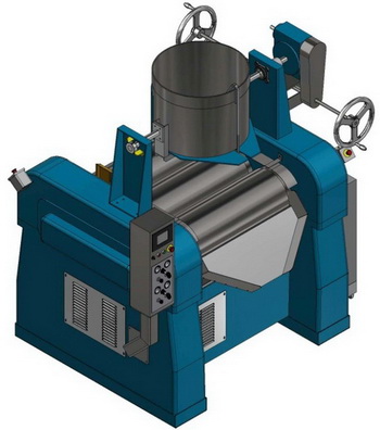
Although can tilters are typically used for viscous paste inks, they also work well for liquid inks. There are basically three (3) mounting positions for a can tilter. Most typically, the can tilter is mounted on the shoulders of the TRM, and it tilts toward the feed side of the TRM, pouring into the feed nip. As a can tilter can accept different size ink tubs, it must be situated, so that the largest ink tub pours onto the feed roll, while the smallest ink tub pours onto the center roll. A can tilter can also be mounted on a platform behind the feed side of the TRM, and in this case it tilts toward the apron, pouring into the feed nip. In this mounting position, the largest ink tub pours onto the center roll, and the smallest ink tub pours onto the feed roll. The third mounting position has the can tilter mounted on a single shoulder, with the largest and smallest ink tubs all pouring directly into the feed nip. The drawings to the right and below show the two most typical mounting positions.
The typical can tilter has two vertical supports, the tilting table, a gearbox, and two hand wheel shafts that allow the operator to pour ink from either the apron side, or the feed side of the TRM. tilter. Although almost all can tilters are manually operated, some are driven electrically, while others are driven hydraulically.
The ink tub can be loaded onto the can tilter in two ways. Mostly, this is done using a forklift. The second option is to have a series of TRMS located under an overhead crane system. In this case, all the ink tubs will have “ears”, and the crane will have a “spreader bar assembly” that is used to pick up the ink tubs, by the two ears. 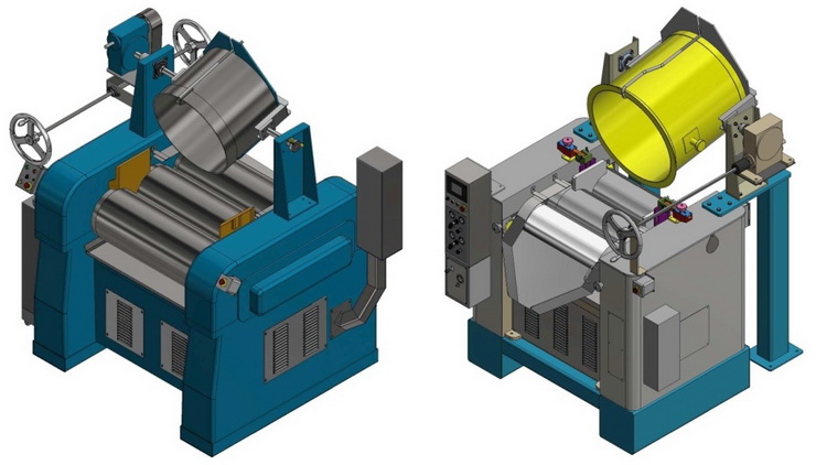
HYDRAULIC PRESS OUTS
As with can tilters, although hydraulic press out systems (HPOS) are typically used for viscous paste inks, they also work well for liquid inks. These HPOS all lock onto the top of a specially designed / heavy duty ink tub, and they have a down acting piston, driven by a small hydraulic power-pack. Most HPOS are post mounted. In this case, the ink tub is rolled into place, and it is locked onto the head of the HPOS. The assembled HPOS is then raised approx. 3 or 4 feet, via an electric chain hoist. Then the assembled HPOS is rotated 90 degrees, allowing the discharge pipe to be positioned over the feed nip. Once these steps have occurred, the assembled HPOS is ready for us
Other HPOS units will not utilize a post lift. In this case, the HPOS is locked onto the ink tub, and then assembled HPOS is raised onto a platform above the TRM for use. The assembled HPOS can also just be positioned, on the ground, behind the feed side of the TRM. In this case, a long feed hose is required to bring ink to the feed nip, and since this long feed hose is difficult to clean, this configuration is not seen often. When it is seen, many times the system is used for only one product, and the hose is just capped at the end of the run.
Although the HPOS can be operated manually, more typically it is controlled via an ink level sensing system on the TRM. This system will have three (3) set points. The lowest is the low level shut off. The middle set point tells the HPOS to send ink, while the highest set point tells the HPOS to stop sending ink. The photo below shows a typical HPOS.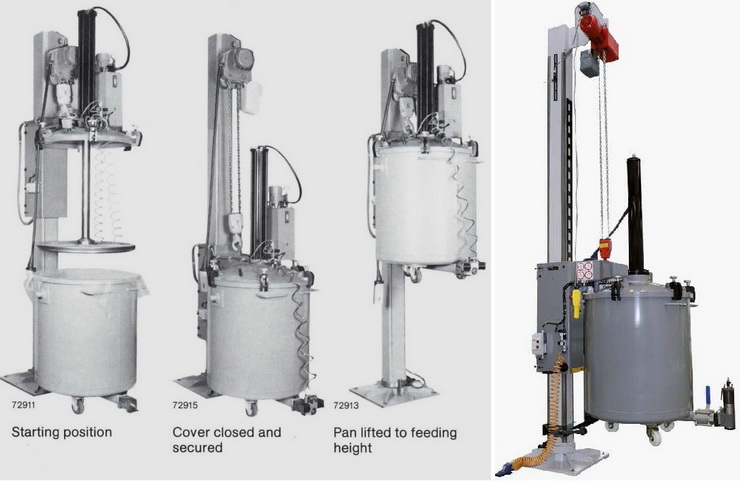
PUMPS
Pumps are typically used when a single product is run on a TRM, due to the difficulty in cleaning the hose. Like with the HPOS systems, pumps are typically controlled via an ink level sensing system on the TRM. This system will have three (3) set points. The lowest is the low level shut off. The middle set point tells the HPOS to send ink, while the highest set point tells the HPOS to stop sending ink. 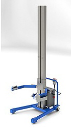
PORTABLE TUB TILTERS
There are any number of portable carts that have been used as “ink tub tilters”. In all cases, the ink tub is locked into place on the device, and then the device is moved to the feed side of the TRM. The device then raises the ink tub above the level of the feed roll, and then the device moves inward toward the feed roll, to a point where when it is tipped, the ink will pour into the feed nip. Most of these devices have manual positioning, electro-mechanical or electro-hydraulic raising and tilting. The photo at the right shows one such device.
POST LIFTS
Post lifts are found throughout the pharmaceutical industry, and they are used for many applications. They consist of a stationary post that can rotate through either 90 degrees, or 180 degrees. The post has an electro-mechanical lifting mechanism, attached to a system that “holds” a stainless steel drum. The system that “holds” the drum, has a secondary electro-mechanical system that can tilt the drum for discharge. In practice, the drum is brought to the post lift and attached. It is then raised to the proper discharge height, and then the post is rotated either 90 or 180 degrees. Once in the correct position, the drum is tilted over for discharge of the pharmaceutical product. For the ink industry, an ink tub substitutes for the stainless steel drum, and ink substitutes for the pharmaceutical product. The photo below shows a typical post lift.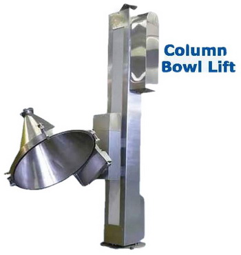
POUR STATION
Pour stations are used for low viscosity inks that can flow out of a bottom outlet on an ink tub. Typically these pour stations are mounted on a mill shoulder, and they pour into the feed nip. These can have a manual valve, or they can have a solenoid valve that work in conjunction with ink level sensing system on the TRM.
PREWIRE OPTIONS
All TRMs sold by KMC are fully ANSI 2017 (B177.1-2017) compliant. The KMC electrical package is fully ANSI 2017 (B177-1-2017) compliant, with variable roll speed, with WASH-UP MODE (a very slow speed that is used when cleaning the rolls), with EMERGENCY BRAKING, and with NGSIS (nip guard safety interlock system that monitors mill functions and insures when cleaning the rolls, the wash-up stick (in-running nip point guard) is in the rear nip, and the mill is in wash-up mode).
The standard KMC electrical package for smaller TRMs has the main electrical box mounted onto the mill frame (motor side), and it includes a column mounted, two sided control station, with color touch screen HMI. It also includes a TEFC inverter duty motor, and NEMA4 enclosure and wiring protocols. The photo below is an example of this package. Since the package is fully prewired, electrical hook up required that only a single power line needs to be brought to the main electrical box.
The standard KMC electrical packages for production TRMs includes a main electrical box, a primary control station with color touch screen HMI, a secondary control station, two (2) E-stop buttons, and a feed roll safety cable assembly. This electrical package includes a TEFC inverter duty motor, and NEMA4 enclosure and wiring protocols.
Please note that on our production size TRMs, the main electrical box is mounted on castors, allowing for easy access to the motor, timing belt drive, etc...
For explosion proof requirements, KMC supplies electrical packages that are ISXP (intrinsically safe explosion proof). The package can be rated for either Class 1/Div 2 or Class 1/Div 1.
PRODUCT LEVEL SENSING FOR THE FEED NIP
The KMC product level sensing system for the feed nip, uses the color touch screen HMI, located in the primary control station, to monitor the level of product in the feed nip. The system has three (3) level set points. The most important set point, is the low level shutoff. As the name implies, if the level of product gets down to the low level shutoff, the system stops the TRM (Note: This is a normal stop that does not engage emergency braking). The low level shutoff is preset at the KMC shop, with a password protected modification procedure for the customer’s engineering department. There is also a spring operated low level bypass switch, located on the secondary control station that is positioned on the feed side of the TRM. This low level bypass switch (used in conjunction with the start button on the secondary control station), allows the operator to “run out” the last bit of material in the feed nip, before opening the rolls for cleaning. The other set points are used when the system is controlling a feeding device (pump, or press-out, or can tilter). These are a midlevel set point that would call for product to be fed to the TRM, and the high level set point that would tell the feeding device to stop the flow of product to the TRM. 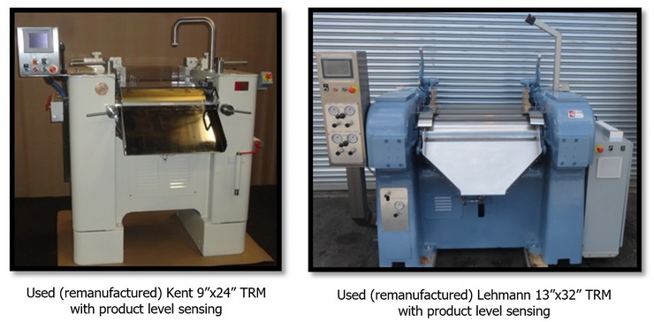
 CONFORMING BASES
KMC supplies bases for TRMS that conform to the footprint of the mill. The purpose of these CONFORMING BASES is to raise the apron discharge height, so as to accommodate a tank. These CONFORMING BASES are typically designed to raise the TRM from 4” to 18”. The KMC design has an extra benefit, as it allows the TRM to be easily moved by an appropriately sized forklift. The photos below show examples of TRMS on CONFORMING BASES.